
MEMTECK
Membrane Technology Solutions

MemTeck™ SWRO-HF 440 8040
Sea Water-High Flux (SWRO-HF) 440 RO Membranes
(Feed Salinity ~32,000 ppm, 800 psi)
Sea Water-High Flux (SWRO-HF) 440 RO Membranes
(Feed Salinity ~32,000 ppm, 800 psi)
Test Conditions: 32,000 ppm NaCl, 800 psi (55.158 bar), pH 8, 77°F (25°C), 15% Recovery
Key Features & Applications
Key Features
- Low Operating Pressure
Contributes to reduced energy consumption. - High Permeate Flow (High Flux)
Designed for increased water production while maintaining excellent salt rejection performance. - Excellent Salt Rejection (≈ 99.5%)
Provides excellent salt rejection at typical seawater salinity (~32,000 ppm TDS). - High Productivity at Lower Feed Pressures
Improves overall system efficiency while reducing operational energy demand. - Advanced proprietary feed-spacer technology minimizes pressure drop, enhances feed flow distribution, and ensures stable long-term performance.
- Superior anti-fouling performance reduces scaling tendency, lowers chemical cleaning frequency, and extends membrane service life.
- Lower overall energy consumption, reducing operating costs.
Applications
- Seawater Desalination
- High-Salinity Brackish Water Treatment
- High-Salinity Surface Water Treatment
- High-Salinity Municipal Wastewater Reuse
- Dairy Industry Water Treatment
- Pharmaceutical Purified Water Production
- Oil & Gas Produced Water Treatment
- Cement Industry Water Reuse
- Steel Industry Wastewater Recycling
Element Dimensions
Dimensions – inches (mm)
1 inch = 25.4 mm
1 inch = 25.4 mm
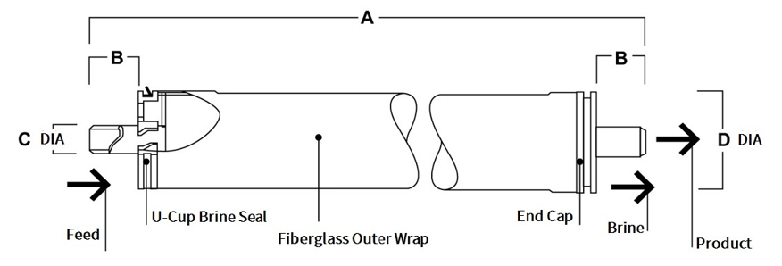
Element Dimensions Reference Table
| Product | A | B | C | D |
|---|---|---|---|---|
| SWRO-HF-8040 | 40.0 (1,016) | 1.19 (30.2) | 1.25 (28.6) | 7.9 (200) |
1. Test conditions: 32,000 ppm NaCl, 800 psi (55.158 bar), pH 8, 77°F (25°C), 15 % recovery.
2. Minimum salt rejection is 98.5 %.
3. Individual elements may have different permeating flows by +/-15%.
2. Minimum salt rejection is 98.5 %.
3. Individual elements may have different permeating flows by +/-15%.
Typical Properties
| Product | Active Membrane Area ft² (m²) | Permeate Flow Rate GPD (m³/d) | Stabilized Salt Rejection % | Feed Spacer mil |
|---|---|---|---|---|
| SWRO-HF 8040 | 440 (41 bar) | 12,000 (45) | 99.5 | 34 |
Operation Specifications and Cleaning Limits
| Specification | SWRO-HF-8040 |
|---|---|
| Membrane Materials | Polyamide Thin-Film Composite |
| Maximum Operating Temperature | 113°F (45°C) |
| Maximum Operating Pressure | 1200 psi (83 bar) |
| Maximum Feed Flow Rate | 75 gpm (17 m³/h) |
| Maximum Pressure Drop | 15 psig (1.0 bar) |
| pH Range | 2 - 11 |
| Maximum Feed Silt Density Index (SDI) | SDI 5 |
| Free Chlorine Tolerance | < 0.1 ppm |
1. Over pH 10, the maximum continuous temperature is 95°F (35°C).
2. In certain conditions, free chlorine and other oxidizing agents can cause premature membrane failure. Pretreatment prior to membrane exposure is recommended.
2. In certain conditions, free chlorine and other oxidizing agents can cause premature membrane failure. Pretreatment prior to membrane exposure is recommended.
General Information
1. After initial wetting, keep elements moist at all times.
2. The limited warranty is void if operating limits are not followed.
3. During prolonged shutdowns, immerse membrane elements in a preservative solution.
4. The customer is responsible for incompatible chemicals and lubricants.
5. Maximum pressure drop across a pressure vessel is 50 psi (3.4 bar).
6. Always avoid static backpressure on the permeate side.
7. Discard the permeate from the first hour of operation.
8. Avoid abrupt pressure or crossflow changes.
9. Protect spiral elements during startup, shutdown and cleaning.
10. Increase feed pressure gradually over 30–60 minutes.
11. Increase crossflow velocity gradually over 15–20 seconds.
12. Ensure correct system design for effective pathogen reduction.
13. Discard first-hour permeate.
14. Follow proper RO startup procedures to prevent hydraulic shock.
15. Complete pretreatment, membrane loading and system checks before startup.
2. The limited warranty is void if operating limits are not followed.
3. During prolonged shutdowns, immerse membrane elements in a preservative solution.
4. The customer is responsible for incompatible chemicals and lubricants.
5. Maximum pressure drop across a pressure vessel is 50 psi (3.4 bar).
6. Always avoid static backpressure on the permeate side.
7. Discard the permeate from the first hour of operation.
8. Avoid abrupt pressure or crossflow changes.
9. Protect spiral elements during startup, shutdown and cleaning.
10. Increase feed pressure gradually over 30–60 minutes.
11. Increase crossflow velocity gradually over 15–20 seconds.
12. Ensure correct system design for effective pathogen reduction.
13. Discard first-hour permeate.
14. Follow proper RO startup procedures to prevent hydraulic shock.
15. Complete pretreatment, membrane loading and system checks before startup.
Regulatory Note
Please check the application status of this product before using or selling it; some countries may restrict its use in drinking water.
Disclaimer
All information is provided for informational purposes only. Product suitability, operating conditions and performance depend on actual application conditions and applicable regulations.
Connect With Us