MEMTECK
Membrane Technology Solutions

MemTeck™ SWRO-LP 4040 & 8040
Sea Water-Low Pressure (SWRO-LP) Membranes
(Feed Salinity up to 20,000 ppm, 300 to 600 psi)
Sea Water-Low Pressure (SWRO-LP) Membranes
(Feed Salinity up to 20,000 ppm, 300 to 600 psi)
Test Conditions: 10,000 ppm NaCl, 350 psig (23.8 bar), pH 8, 77°F (25°C), 15% Recovery
Key Features & Applications
Key Features
-
Superior Salt Rejection (Up to 99.5%)
Provides up to 99.5% salt rejection at feed salinity levels up to 20,000 ppm, with excellent productivity at lower pressures. Specially designed for enhanced salt removal and superior permeate quality. -
Low Operating Pressure
Designed to operate efficiently at reduced feed pressures (300 to 600 psi), minimizing energy consumption while maintaining high productivity and high permeate flow. -
Advanced Feed Spacer Technology
Incorporates proprietary feed spacer design to reduce pressure drop, improve flow distribution, and enhance long-term stable performance. -
Excellent Anti-Fouling Properties
Optimized membrane surface and spacer design improve fouling resistance, resulting in reduced cleaning frequency, lower chemical consumption, reduced energy usage, and extended membrane service life.
Applications
- Highly Saline Brackish Water Treatment: (8,000 to 20,000 ppm TDS)
- Surface Water Treatment: Stable performance under varying conditions.
- Municipal Wastewater Reuse: Supports sustainable water recovery.
- Dairy Processing Applications: Process water & product concentration.
- Pharmaceutical Water Systems: High-purity water requirements.
- Oil & Gas Industry: Engineered for durability and stable operation.
Element Dimensions
Dimensions – inches (mm)
1 inch = 25.4 mm
1 inch = 25.4 mm
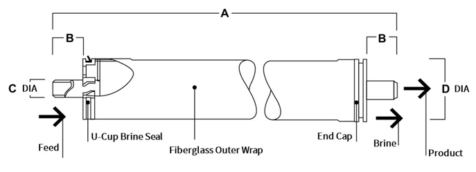
Element Dimensions Reference Table
| Product | A | B | C | D |
|---|---|---|---|---|
| SWRO-LP-4040 | 40.0 (1,016) | 1.05 (26.7) | 0.75 (19) | 3.9 (99) |
| SWRO-LP-8040 | 40.0 (1,016) | 1.19 (30.2) | 1.25 (28.6) | 7.9 (200) |
Typical Properties
| Product | Active Membrane Area ft² (m²) | Permeate Flow Rate GPD (m³/d) | Stabilized Salt Rejection % | Feed Spacer mil |
|---|---|---|---|---|
| SWRO-LP-4040 | 100 (9.2) | 2,600 (9.8) | 99.5 | 28 |
| SWRO-LP-8040 | 400 (37.2) | 8,500 (32) | 99.5 | 28 |
1. Test conditions: 10,000 ppm NaCl, 350 psig (23.8 bar), pH 8, 77°F (25°C), 15% recovery.
2. Minimum salt rejection is 99.1%.
3. Individual elements may have different permeating flows by +/-15%.
2. Minimum salt rejection is 99.1%.
3. Individual elements may have different permeating flows by +/-15%.
Operation Specifications and Cleaning Limits
| Specification | SWRO-LP-4040 | SWRO-LP-8040 |
|---|---|---|
| Membrane Materials | Polyamide Thin-Film Composite | |
| Maximum Operating Temperature | 113°F (45°C) | 113°F (45°C) |
| Maximum Operating Pressure | 600 psi (41 bar) | 600 psi (41 bar) |
| Maximum Feed Flow Rate | 16 gpm (3.6 m³/h) | 75 gpm (17 m³/h) |
| Maximum Pressure Drop | 15 psig (1.0 bar) | 15 psig (1.0 bar) |
| pH Range | 2 - 11 | 2 - 11 |
| Maximum Feed Silt Density Index (SDI) | SDI 5 | SDI 5 |
| Free Chlorine Tolerance | < 0.1 ppm | < 0.1 ppm |
1. Over pH 10, the maximum continuous temperature is 95°F (35°C).
2. In certain conditions, free chlorine and other oxidizing agents can cause premature membrane failure. Pretreatment prior to membrane exposure is recommended to prevent oxidation damage, since oxidation damage is not covered by warranty.
2. In certain conditions, free chlorine and other oxidizing agents can cause premature membrane failure. Pretreatment prior to membrane exposure is recommended to prevent oxidation damage, since oxidation damage is not covered by warranty.
General Information
1. After initial wetting, keep elements moist at all times.
2. The limited warranty will be null and void if the operating limits and guidelines are not strictly followed.
3. For the purpose of preventing biological growth during prolonged system operation shutdowns, membrane elements should be immersed in a preservative solution.
4. The customer is fully responsible for the effects of incompatible chemicals and lubricants on elements.
5. The maximum pressure drop across an entire pressure vessel (housing) is 50 psi (3.4 bar).
6. Always avoid static backpressure on the permeate side.
7. The permeate obtained from the first hour of operation should be discarded.
8. Make sure there are no abrupt changes in pressure or crossflow.
9. During start-up, shutdown, cleaning, or other sequences, spiral elements should be protected from damage. It is recommended to gradually transition from a standstill to an operating state during startup.
10. The feed pressure should be gradually increased over a 30-60-minute period.
11. The crossflow velocity should be gradually increased over 15-20 seconds to reach the set operating point.
12. It is crucial that the system is designed and operated correctly in order to reduce cysts and pathogens effectively.
13. The permeate obtained from the first hour of operation should be discarded.
2. The limited warranty will be null and void if the operating limits and guidelines are not strictly followed.
3. For the purpose of preventing biological growth during prolonged system operation shutdowns, membrane elements should be immersed in a preservative solution.
4. The customer is fully responsible for the effects of incompatible chemicals and lubricants on elements.
5. The maximum pressure drop across an entire pressure vessel (housing) is 50 psi (3.4 bar).
6. Always avoid static backpressure on the permeate side.
7. The permeate obtained from the first hour of operation should be discarded.
8. Make sure there are no abrupt changes in pressure or crossflow.
9. During start-up, shutdown, cleaning, or other sequences, spiral elements should be protected from damage. It is recommended to gradually transition from a standstill to an operating state during startup.
10. The feed pressure should be gradually increased over a 30-60-minute period.
11. The crossflow velocity should be gradually increased over 15-20 seconds to reach the set operating point.
12. It is crucial that the system is designed and operated correctly in order to reduce cysts and pathogens effectively.
13. The permeate obtained from the first hour of operation should be discarded.
Important Information
14. To prevent membrane damage due to overfeeding or hydraulic shock, it is essential to start up reverse osmosis water treatment systems properly. As a result of following the proper start-up sequence, system water quality and productivity goals can also be achieved.
15. Pretreatment of the membrane, loading of the membrane elements, instrument calibration, and other system checks should be completed before starting the system.
15. Pretreatment of the membrane, loading of the membrane elements, instrument calibration, and other system checks should be completed before starting the system.
Regulatory Note
Please check the application status of this product before using or selling it; some countries may restrict the use of this product in drinking water.
Disclaimer
Herein, all information is provided purely for informational purposes. It is important to note that this is general information and that it may differ depending on actual conditions.
As a customer, you are responsible for making sure that the products and information contained in this document are appropriate for use by you and that your workplace and disposal practices comply with applicable laws.
There may be geographic restrictions on the sale of the product shown in this literature. It is possible that the claims made have not been approved for use in all countries.
In this document, operating conditions are intended to extend product lifespan and/or improve product performance, but they will ultimately depend on actual circumstances and are never a guarantee that any specific results will be achieved. Physical properties may vary depending on certain conditions. This document is provided without any obligation or liability on the part of Memteck.
As a customer, you are responsible for making sure that the products and information contained in this document are appropriate for use by you and that your workplace and disposal practices comply with applicable laws.
There may be geographic restrictions on the sale of the product shown in this literature. It is possible that the claims made have not been approved for use in all countries.
In this document, operating conditions are intended to extend product lifespan and/or improve product performance, but they will ultimately depend on actual circumstances and are never a guarantee that any specific results will be achieved. Physical properties may vary depending on certain conditions. This document is provided without any obligation or liability on the part of Memteck.
Connect With Us